Part 2 of 3: Positional Correction on Color Print Rollers in Offset Printing
Introduction
This is the second of three advanced electronic gearing topics discussed in this series of papers. The first paper covered tension control on a spindle, while the third will cover writing on a moving conveyor system. To view Part 1 click HERE.
Definition
This topic covers positional corrections of geared color print rollers on a web style, offset printing machine. Figure 1 shows material being pulled through three printing rollers, each a different color. The second and third rollers are geared to the first with a 1:1 ratio. Each roller must be properly aligned so that as the material is pulled through, the printed colors line up. In a perfect world, this can be calculated knowing the distance in-between rollers and the radius of the rollers.
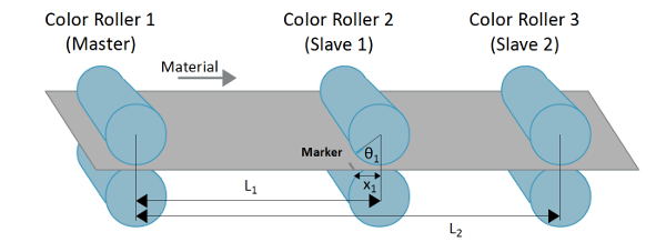
Figure 1: Web printing diagram
Color Roller 1 is the master axis and reference point as the material is pulled through the system. Color Roller 2 is geared to Color Roller 1 and prints so that it is L1 distance behind the printing of Color Roller 1. From a theoretical standpoint, this timing can be easily calculated knowing the distance L1 and the radius of Color Roller 2. The same can be applied to Color Roller 3 using the distance L2 from the master axis.
The challenge comes from the variations in the material length due to stretch as it is pulled through the printer. Therefore, if a certain location is tracked on the material (shown by the gray marker in Figure 1), it may not line up with the exact angle of Color Roller 2 as it passes through. The outcome would show a color misalignment if not accounted for.
To resolve this, a marker must be placed on the material and measured before Color Roller 2, so that the roller can correct its position, θ1, to be aligned properly as the marker passes through Color Wheel 2.
Resolution
This section will first cover the system implementation to correct for these variations, and then apply the implementation using a Galil DMC-4030 motion controller.
System Implementation
Figure 2 shows the same system as Figure 1 with three additions. First, the master axis lays down a marker in the margin of the material, establishing a reference. The last two additions include two sensors to read that marker, one before each of the slave axes.
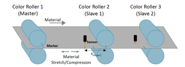
Figure 2: Web printing diagram with sensors for phase correction
The system is then designed based on the calculations, assuming no material stretch or compression, since all distances between color rollers are known along with the radius of the rollers. As the marker passes through the first sensor, Color Roller 2 can adjust its position (or phase). Adjusting its phase will enable Color Roller 2 to properly align its angle so that as the marker passes through the roller the second color will properly align with the first color. Likewise, the same principle can be applied to Color Roller 3. This assumes that all rollers home to a known position before operation.
There are two ways the slave axis can correct: using a step move or using a profiled move. The step move is a sudden and instantaneous correction in the slave's profile, while the profiled move is a correction that is generated with a certain speed and acceleration/deceleration. The sensor must be placed far enough before the roller to allow for the correction to take place before the marker passes through the roller.
Galil Implementation
The initial setup for this application is to initialize gearing. For this example, Galil's DMC-4030, 3-axis motion controller is used. The axes A, B, and C defined on the DMC-4030 represent Color Rollers 1, 2, and 3 respectively. Code 1 sets up axes B and C to be geared to the commanded position of axis A with a gear ratio of 1:1.
#gear
GAB= CA;'Axis B is geared to commanded position of Axis A
GAC= CA;'Axis C is geared to commanded position of Axis A
GR ,1,1;'gear ratio of B and C is 1:1
Code 1: DMC-4030 initialize gearing
The next aspect of this implementation is measuring the phase correction. Knowing the appropriate distances of the sensors, the radius of the rollers, encoder resolution of the rollers, etc, the calculations can be performed for the phase angle, in encoder counts. Therefore, at that time, the actual position of the slave needs to be captured to find the phase amount to correct for.
phasecorrect=phasecalculated-phasemeasured
Equation 1: Phase correction
With Galil controllers, this position capture can easily be obtained using position latch. Position latch will capture the encoder position for an axis upon a defined edge trigger of a digital input. Each axis has an individual input for latch, and therefore, both slave axes (and more) can capture independent of one another. The AL command arms the latch, and the RL command reports the latched position. Code 2 demonstrates the position latch functionality.
'Color Roller 2 (B axis)
#corB;'Axis B correction routine
AL B;'arm B axis position latch
#latchB;JP #latchB,(_ALB=1);'wait until latch has occurred
corB= theta1-(_RLB%4000);'calculate phase difference
Code 2: Position latch of axis B
The phase calculation for Color Roller 3 can be performed in a separate thread as seen in Code 3:
'Color Roller 3 (C axis)
#corC;'Axis C correction routine
AL C;'arm C axis position latch
#latchC;JP #latchC,(_ALC=1);'wait until latch has occurred
corC= theta2-(_RLC%4000);'calculate phase difference
Code 3: Position latch for axis C
The last aspect of this implementation is to correct for the phase error. This is done with the increment position (IP) command as shown in Code 4:
'Color Roller 2 (B axis)
#corB;'Axis B correction routine
AL B;'arm B axis position latch
#latchB;JP #latchB,(_ALB=1);'wait until latch has occurred
corB= theta1-(_RLB%4000);'calculate phase difference
IPB= corB;'correct phase difference
JP #corB;'repeat correction routine
EN
Code 4: Axis B phase correction
And for axis C:
'Color Roller 3 (C axis)
#corC;'Axis C correction routine
AL C;'arm C axis position latch
#latchC;JP #latchC,(_ALC=1);'wait until latch has occurred
corC= theta2-(_RLC%4000);'calculate phase difference
IPC= corC;'correct phase difference
JP #corC;'repeat correction routine
EN
Code 5: Axis C phase correction
As mentioned in the first paper in this series, Tension Control on Spindle Wheel, independent positional moves, such as IP, are superimposed to the geared profile of the slave. Therefore, axes B and C continue to track the master axis as the IP command is a corrective move applied on top of the geared profile.
The IP command can also provide two different functionalities. The default functionality is a profiled move with a defined speed and acceleration/deceleration. SP sets the speed, AC sets the acceleration, and DC sets the deceleration.
Additionally, if the axis is commanded with the jog (JG) command, the IP command will instead perform a step move. Therefore, if a step correction is desired, Code 6 can be used to initialize the axis to perform a step profile upon IP.
#gear
GAB= CA;'Axis B is geared to commanded position of Axis A
GAC= CA;'Axis C is geared to commanded position of Axis A
GR ,1,1;'gear ratio of B and C is 1:1
JG ,0,0;'initialize jog with speed 0 for B and C axes
BG BC;'begin jog
Code 6: Initialization for step move with IP
Figure 3 shows a step profile phase correction of 15 encoder counts for Color Roller 2. The green trace is the state of the latch (when the marker is triggered), the red is the profiled velocity of the master, the blue is the profiled velocity of the slave (axis B), and the purple is the following error of the slave axis.
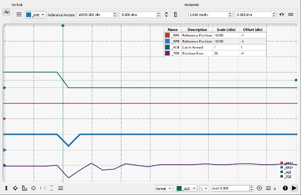
Figure 3: Instantaneous phase correction
Once the marker is detected by the latch input (green), the controller calculates and performs the proper phase correction as seen by the slave axis velocity (blue). The position error (purple) has a sudden jump due to the step correction, but quickly settles in about 10 msec.
Conclusion
This example application can be expanded to making high-speed positional corrections for various types of applications that use gearing. Galil controllers can easily simplify this type of application at high speeds.
Moreover, the first paper in this series, Tension Control on Spindle Wheel, demonstrated that lower-bandwidth feedback loop can be used over the position loop to correct for system frequency (example given: tension). In that paper, the tension loop was closed by varying the speed of the motor. An important correlation can be made from these first two papers. The two important measurements in a system response are frequency and phase. For motion control, frequency and phase correspond to speed and position. In the first paper, the motor speed was varied to correct for frequency, and with this paper, motor position was varied to correct for phase.